
. . . . . . . Do these wires go? Probably many a question that has been asked by many restorers over the years. And still being asked even now as has been seen on many vintage/antique motorcycle website notice boards. So we have decided to try and help vintage restorers/owners out there by putting up some basic circuit diagrams of early motorcycle charging systems.
The 3 main manufacturers of charging equipment for English motorcycles were Lucas of Birmingham, and M.L. Syndicate of Coventry, and Miller.
Maglita, manufactured by M.L. were later taken over by Lucas who then supplied superceded charging units.
There are 2 types of early charging systems, the 3 brush generator with the shunt or half charge resistor, and the later 2 brush generator with the Automatic Voltage Control unit.
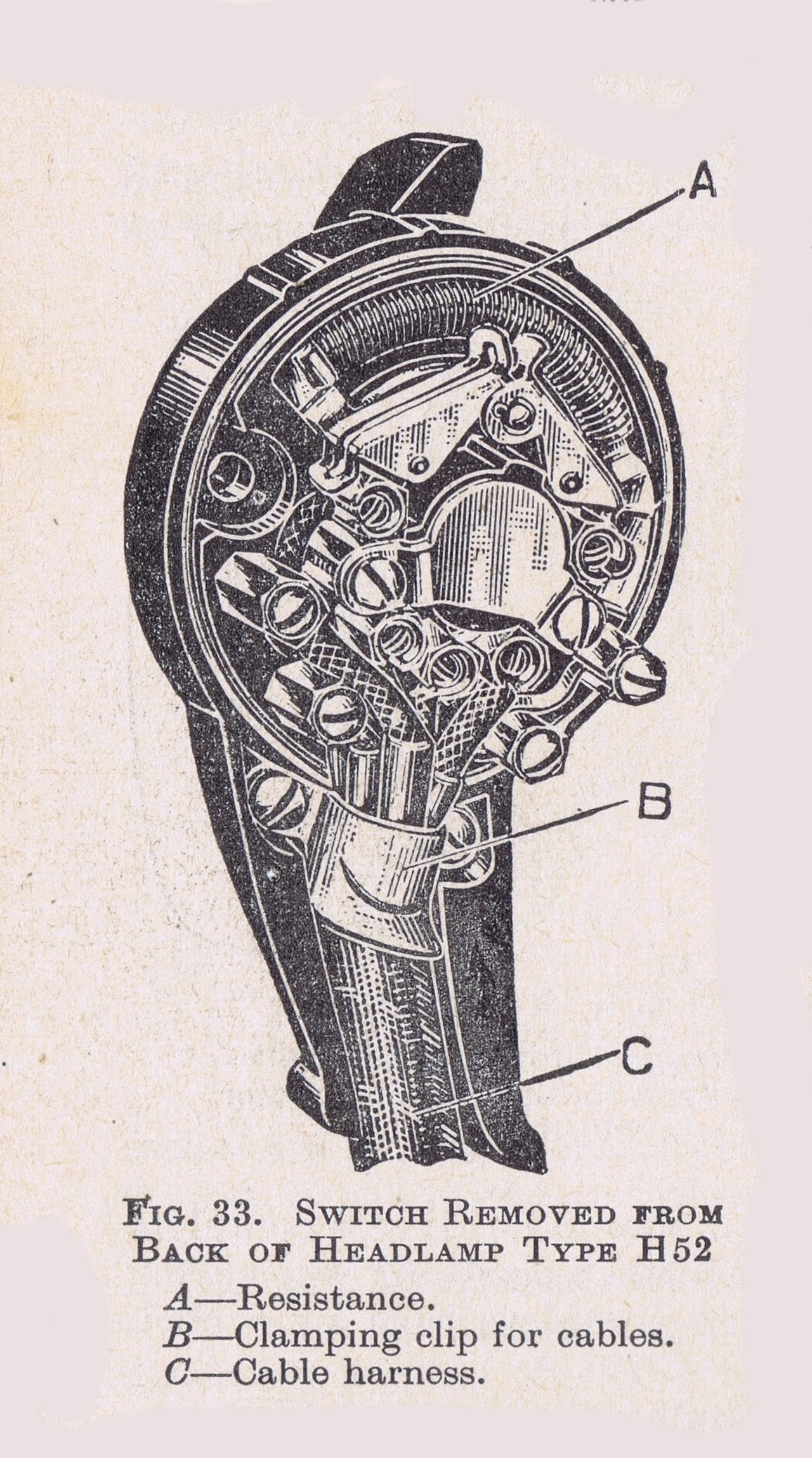
A drawing of the rear of a 1930s light switch clearly showing the early half charge resistor.
Even though the wiring diagrams were copied from marque manuals like Royal Enfield, Triumph, Rudge, Matchless and the like they were actually provided by the electrical suppliers of the time, ie Lucas and Miller. There seemed to be a standardization in the wiring diagrams between the different marques which has resulted in us assembling the 12 most common circuits used, hopefully these will be of use to those who can pick up a soldering iron. There are the odd charging systems out there that are not covered by this article, for example 1920s/30s Douglas pancake generator made by BTH that no other manufacturer seemed interested in employing, but for the main hopefully our effort here will cover about 90% of English motorcycles.
Of course a lot of 1930s motorcycle charging systems with resistor half charging current control could have been upgraded to the later Automatic Voltage Control charging systems, of which one of the later wiring diagrams would be more applicable. You will need to study the circuitry very closely, but am sure that there will be something there that will be of value.
We have provided what would be the main wiring diagrams that were used on late 1920 to 30s English motorcycles
In order the wiring diagrams are –
1) Lucas 1930 Magdyno 3 Brush with half charge resistor
2) Lucas 1933 Magdyno, no Automatic Voltage Control with half charge resistor
3) Lucas 1935 Coil Ignition, no Automatic Voltage Control with half charge resistor
4) Lucas 1935 Magdyno, with no Automatic Voltage Control with half charge resistor
5) Lucas 1936 Dynamo and Coil Ignition with Automatic Voltage Control
6) Lucas 1937 Magdyno with Automatic Voltage Control
7) Lucas 1938 Magdyno with Automatic Voltage Control
8) Lucas 1946 with Automatic Voltage Control
9) Lucas M.L. Maglita for Matchless, Rudge
10) Miller Coil Ignition, Panthers with half charge resistor
11) Miller Magneto Ignition, Panthers with half charge resistor
12) Miller Magneto Ignition, Rudge with half charge resistor.
The file is a PDF. Just click on Mr Lucas below to view it.
You can also click on the following to see additional wiring diagrams and dynamo information for –
1919 Running Instructions for Lucas Dynamo Lighting Set for Motorcycles.
1935 Maintenance and Running Instructions for Miller Lighting and Coil Ignition Systems.
We are aware that for a lot of vintage riders night riding is not an issue as the modern traffic and drivers can make it unsafe to do so, so choose not to. There are others that because of the challenge to get parts for older underpowered charging systems have choosen to disconnect the generator and just connect up a small gel battery that is charged externally, should they need some lights for that short ride home as darkness approaches.
A few principles to follow to ensure trouble free electrical systems –
1) Stay away from those cheap blue and red crimp lugs that besides looking horrible are open to the weather for corrosion to set in.
2) The original wiring diagrams do not show a fuse but it would be prudent to install one. It could save serious risk from fire should a short circuit happen. The best place is to install it in either the positive or negative leads connected to the battery.
3) Do not rely on the return earth path from the headlight to go through the steering head bearings or reply on the clutch cable. To increase reliability run a separate earth wire from the battery earth terminal through to the headlight, even though the circuit diagrams don’t actually show it. Passing electrical current through any bearings causes premature failure of that bearing.